- 您现在的位置:买卖IC网 > Sheet目录299 > 71M6511H-IGTR/F (Maxim Integrated)IC ENERGY METER RESIDENT 64-LQFP
�� �
�
�71M6511/71M6511H�
�Single-Phase� Energy� Meter� IC�
�A� Maxim� Integrated� Products� Brand�
�DATA� SHEET�
�NOVEMBER� 2010�
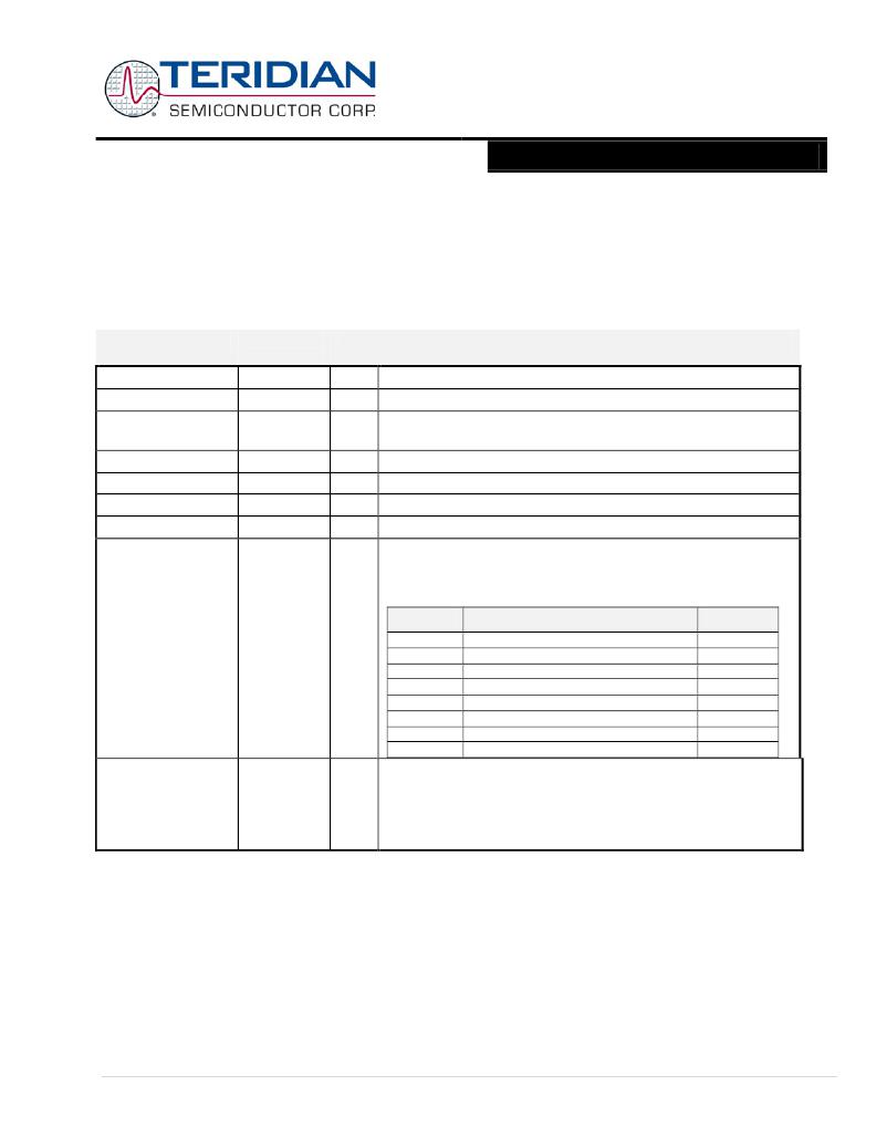
�I/O� RAM� (Configuration� RAM)� –� Alphabetical� Order�
�Many� functions� of� the� chip� can� be� controlled� via� the� I/O� RAM� (Configuration� RAM).� The� CE� will� also� take� some� of� its� para-�
�meters� from� the� I/O� RAM.�
�Bits� with� a� W� (write)� direction� are� written� by� the� MPU� into� I/O� RAM.� Typically,� they� are� initially� stored� in� flash� memory� and�
�copied� to� the� I/O� RAM� by� the� MPU.� Some� of� the� more� frequently� programmed� bits� are� mapped� to� the� MPU� SFR� memory�
�space.� The� remaining� bits� are� mapped� to� 2xxx.� Bits� with� R� (read)� direction� can� only� be� read� by� the� MPU.� On� power� up,� all�
�bits� are� cleared� to� zero� unless� otherwise� stated.� Generic� SFR� registers� are� not� listed.�
�Name�
�Location�
�Dir�
�Description�
�[Bit(s)]�
�ADC_DIS�
�CE_EN�
�CHOP_EN[1:0]�
�2005[3]�
�2000[4]�
�2002[5:4]�
�R/W�
�R/W�
�R/W�
�Disables� ADC� and� removes� bias� current�
�CE� enable.�
�Chop� enable� for� the� reference� band� gap� circuit.�
�00:� enabled� 01:� disabled� 10:� disabled� 11:� enabled�
�RESERVED�
�CKOUT_DIS�
�RESERVED�
�RESERVED�
�DIO_R4[2:0]�
�DIO_R5[2:0]�
�DIO_R6[2:0]�
�DIO_R7[2:0]�
�2004[5]�
�2004[4]�
�2003[4:3]�
�2003[2:0]�
�200B[2:0]�
�200B[6:4]�
�200C[2:0]�
�200C[6:4]�
�R/W�
�R/W�
�R/W�
�R�
�R/W�
�R/W�
�R/W�
�R/W�
�Must� be� 0.�
�CKOUT� Disable.� When� zero,� CKTEST� is� an� active� output.�
�Must� be� 0.�
�Reserved�
�Connects� dedicated� I/O� pins� 4� to� 11� to� selectable� internal� resources.� If�
�more� than� one� input� is� connected� to� the� same� resource,� the� ‘Multiple’�
�column� below� specifies� how� they� are� combined.� See� Software� User’s�
�Guide� for� details).�
�DIO_R8[2:0]�
�DIO_R9[2:0]�
�DIO_R10[2:0]�
�DIO_R11[2:0]�
�200D[2:0]�
�200D[6:4]�
�200E[2:0]�
�200E[6:4]�
�R/W�
�R/W�
�R/W�
�R/W�
�DIO_GP�
�0�
�1�
�Resource�
�NONE�
�Reserved�
�Multiple�
�--�
�OR�
�2�
�3�
�4�
�5�
�6�
�7�
�T0� (counter0� clock)�
�T1� (counter1� clock)�
�High� priority� I/O� interrupt� (int0� rising)�
�Low� priority� I/O� interrupt� (int1� rising)�
�High� priority� I/O� interrupt� (int0� falling)�
�Low� priority� I/O� interrupt� (int1� falling)�
�OR�
�OR�
�OR�
�OR�
�OR�
�OR�
�DIO_DIR0[7:4]�
�SFR� A2�
�R/W�
�Programs� the� direction� of� DIO� pins� 7� through� 4.� 1� indicates� output.�
�Ignored� if� the� pin� is� not� configured� as� I/O.� See� DIO_PV� and� DIO_PW�
�for� special� option� for� DIO6� and� DIO7� outputs.� See� DIO_EEX� for� special�
�option� for� DIO4� and� DIO5.�
�Note:� Bit� 0,� Bit� 1,� Bit� 2� and� Bit� 3� must� be� set� to� 1.�
�Page:� 59� of� 98�
�?� 2005–2010� Teridian� Semiconductor� Corporation�
�V2.7�
�发布紧急采购,3分钟左右您将得到回复。
相关PDF资料
71M6513H-IGT/F
IC ENERGY METER 3PH 100-LQFP
71M6515H-IGT/F
IC ENERGY METER AFE 3PH 64-LQFP
71M6521BE-IGTR/F
IC ENERGY METER 8K FLASH 64-LQFP
71M6533G-IGTR/F
IC ENERGY METER 3PH 100LQFP
71M6543F-IGT/F
IC ENERGY METERING
71M6545-IGT/F
IC ENERGY METERING
720-10007-00300
CBL D-SUB 9PIN FMAL-25PIN FML 3M
720-10010-00025
CBL DSUB 9PIN FML-25PIN MAL .25M
相关代理商/技术参数
71M6511-IGT
制造商:TERIDIAN 制造商全称:TERIDIAN 功能描述:Single-Phase Energy Meter IC
71M6511-IGT/F
功能描述:计量片上系统 - SoC Highly Integrated SoC w/MCU Core RoHS:否 制造商:Maxim Integrated 核心:80515 MPU 处理器系列:71M6511 类型:Metering SoC 最大时钟频率:70 Hz 程序存储器大小:64 KB 数据 RAM 大小:7 KB 接口类型:UART 可编程输入/输出端数量:12 片上 ADC: 安装风格:SMD/SMT 封装 / 箱体:LQFP-64 封装:Reel
71M6511-IGT/F1
功能描述:计量片上系统 - SoC
RoHS:否 制造商:Maxim Integrated 核心:80515 MPU 处理器系列:71M6511 类型:Metering SoC 最大时钟频率:70 Hz 程序存储器大小:64 KB 数据 RAM 大小:7 KB 接口类型:UART 可编程输入/输出端数量:12 片上 ADC: 安装风格:SMD/SMT 封装 / 箱体:LQFP-64 封装:Reel
71M6511-IGTR
制造商:TERIDIAN 制造商全称:TERIDIAN 功能描述:Single-Phase Energy Meter IC
71M6511-IGTR/F
功能描述:计量片上系统 - SoC Highly Integrated SoC w/MCU Core RoHS:否 制造商:Maxim Integrated 核心:80515 MPU 处理器系列:71M6511 类型:Metering SoC 最大时钟频率:70 Hz 程序存储器大小:64 KB 数据 RAM 大小:7 KB 接口类型:UART 可编程输入/输出端数量:12 片上 ADC: 安装风格:SMD/SMT 封装 / 箱体:LQFP-64 封装:Reel
71M6511-IGTR/F1
功能描述:计量片上系统 - SoC
RoHS:否 制造商:Maxim Integrated 核心:80515 MPU 处理器系列:71M6511 类型:Metering SoC 最大时钟频率:70 Hz 程序存储器大小:64 KB 数据 RAM 大小:7 KB 接口类型:UART 可编程输入/输出端数量:12 片上 ADC: 安装风格:SMD/SMT 封装 / 箱体:LQFP-64 封装:Reel
71M6512-DB
制造商:Maxim Integrated Products 功能描述:Development Boards & Kits - 8051 71M6512 Demo Brd
71M6512-IM/F
制造商:Maxim Integrated Products 功能描述:Metering Systems on a Chip - SoC Residential Meter Extended Io